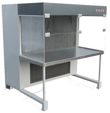
Laminar Air Flow (LAF) Work Station is capable of maintaining a particulate free work area even when operated in an uncontrolled environment. This is achieved by total removal of air borne droplet nuclei and dust-borne bacteria by unidirectional oriented streamlines of clean air at velocities designed to flush contaminating particulates.
Prerequisites before PQ:
- All instrument like magnehelic gauges should calibrated before PQ
- DQ, IQ & OQ should completed before PQ.
The following tests shall be carried out by for PQ of LAF:
- Filter integration and installation leak test
- Air velocity
- Air particulate matter counts (Non viable & Viable)
- Air flow pattern
Filter Integrity
The HEPA Filters Integrity Test carried out before particle count test.
Chemical Used: PAO (Poly Alfa olefin )
Procedure
- Filter test shall be performed only after operational air velocities have been verified and adjusted wherever necessary.
- Position the smoke generator and introduce PAO smoke into the air stream, ahead of the HEPA filters, at the concentration of 80 – 100 mg per liter of air at the filter’s designed air flow rating and set the instrument at 100% concentration.
- Scan the down stream side of the filter with an appropriate photometer probe at a sampling rate of at least 1 ft3 / min.
- The probe should scan the entire filter face and frame at a position about 1 to 2 inches from the face of the filter. Scanning shall be done at the rate of maximum 2 feet per minute.
Acceptance Criteria
- During scanning percentage of the PAO penetration shown by photometer should be less than 0.001% through the filter media and should be “zero” through mounting joints.
Air velocity
Equipment and Instrument: Anemometer
Procedure
- These test are executed on LAF work bench.
- Anemometer range as 0 – 1500 FPM
- Air velocity measured at 4 corners of the LAF as shown below and recording shall be done at V1, V2, V3 and V4 Calculate the average velocity.
V1 V2
V3 V4
- Record the readings in following table:
S. No. Date Equipment HEPA filter Size mm Area Air Velocity (FPM)
Average Velocity (FPM V1 V2 V3 V4 - Measurement should be taken for a minimum of 15 seconds.
- Calculate the number of Air changes in each area by following below given calculation:
Calculations
- Total Air Flow CFM = FPM X Area of Diffuser / Grill in Sq. ft.
Where, FPM is Feet per minute, CFM is Cubic Feet per minute
- Number of Air Changes per hour = Total CFM X 60 Volume of Room (ft3)
Acceptance Criteria
Air velocity should be 90 ± 20 feet/minute
Air particulate matter counts (Non viable & Viable)
Non Viable Count
Perform the test from 5 different locations. Not more than 100 particles of size more than or equal to 0.5 micron per cubic feet of sampled air is allowed.
Viable Count
Expose plates under the Laminar Airflow at the time of qualification.
Acceptance Criteria
Total Microbial Count should be Less than one.
Air Flow Pattern
Equipment & Chemical Used : White visible or yellow smoke generator, Carbon tetra chloride or dry ice for smoke generation
Procedure
- Generate TiCl4 smoke and check whether the system operates as per the desired operating parameters and observe the airflow pattern at the critical locations.
- A critical location is defined as an area where product or material is exposed to the working environment.
- Ensure that the blower sucks the smoke through the return air filter.
Acceptance Criteria
The airflow movement should be from Supply filter Diffuser to the Return Air Grill / Riser and most Positive area to the Negative area.
All the above test parameters shall be qualified for its performance in “at rest” condition where no actual activity shall be performed under the LAF work station.
Re validation
Un Scheduled Re validation :
- Re validate the equipment in the following cases.
- Change of location.
- Break down of Critical parts.
Scheduled Re validation :
- Particle count test and air velocity shall be carried out for every six months.
- DOP test shall be carried out once in a year.
- Plate Exposure shall be carried out for every 15 days.
Recording
After completion of each study, a report shall be prepared by the validation team members which shall include the following information.
- Tabulated Data
- Trend Analysis Plots
- Validation Team Members and their Signatures
- Conclusions
- Quality Assurance Department Certification


